10+ recursive er diagram
In those cases a relationship with its corresponding entities is aggregated into a higher level entity. Here the same entity type participates more than once in a relationship type with a different role for each instance.

Top 24 Data Modelling Interview Questions With Detailed Answers
Learn from diagram examples and start creating your diagrams online.

. Learn about ER diagram symbols how to draw ER diagrams best practices to follow when drawing ER diagrams and ERD examples. ER Diagram tutorial. ER Diagram of Bank Management System.
Cardinality and ordinality are two other notations used in ER diagrams to further define relationships. An entity relationship model also called an entity-relationship ER diagram is a graphical representation of entities which will become your tables and their. One recursive roleis important February 11 2018 Entity-Relationship ER Diagrams 23 STUDENT DEPT FACULTY CHAIR_F Students may have any number of departments in which they minor.
The entities are denoted by rectangle and relationships by diamond. One to one When each entity in each entity set can take part only once in the relationship the cardinality is one to oneLet us assume that a male can marry to one female and a female can marry to one. Utilize a recursive foreign key A foreign key in a relation that references the primary key values of that same relation Unary MN Relationships.
The Tower of Hanoi also called The problem of Benares Temple or Tower of Brahma or Lucas Tower and sometimes pluralized as Towers or simply pyramid puzzle is a mathematical game or puzzle consisting of three rods and a number of disks of various diameters which can slide onto any rodThe puzzle begins with the disks stacked on one rod in order of decreasing size the. The Entity Relationship Diagram ERD gives a graphical overview. It contains well written well thought and well explained computer science and programming articles quizzes and practicecompetitive programmingcompany interview Questions.
Attributes of Bank Entity are Bank Name Code and Address. Learn about UML BPMN ArchiMate Flowchart Mind Map ERD DFD SWOT PEST Value Chain and more. There may be different valid approaches to an ER diagram.
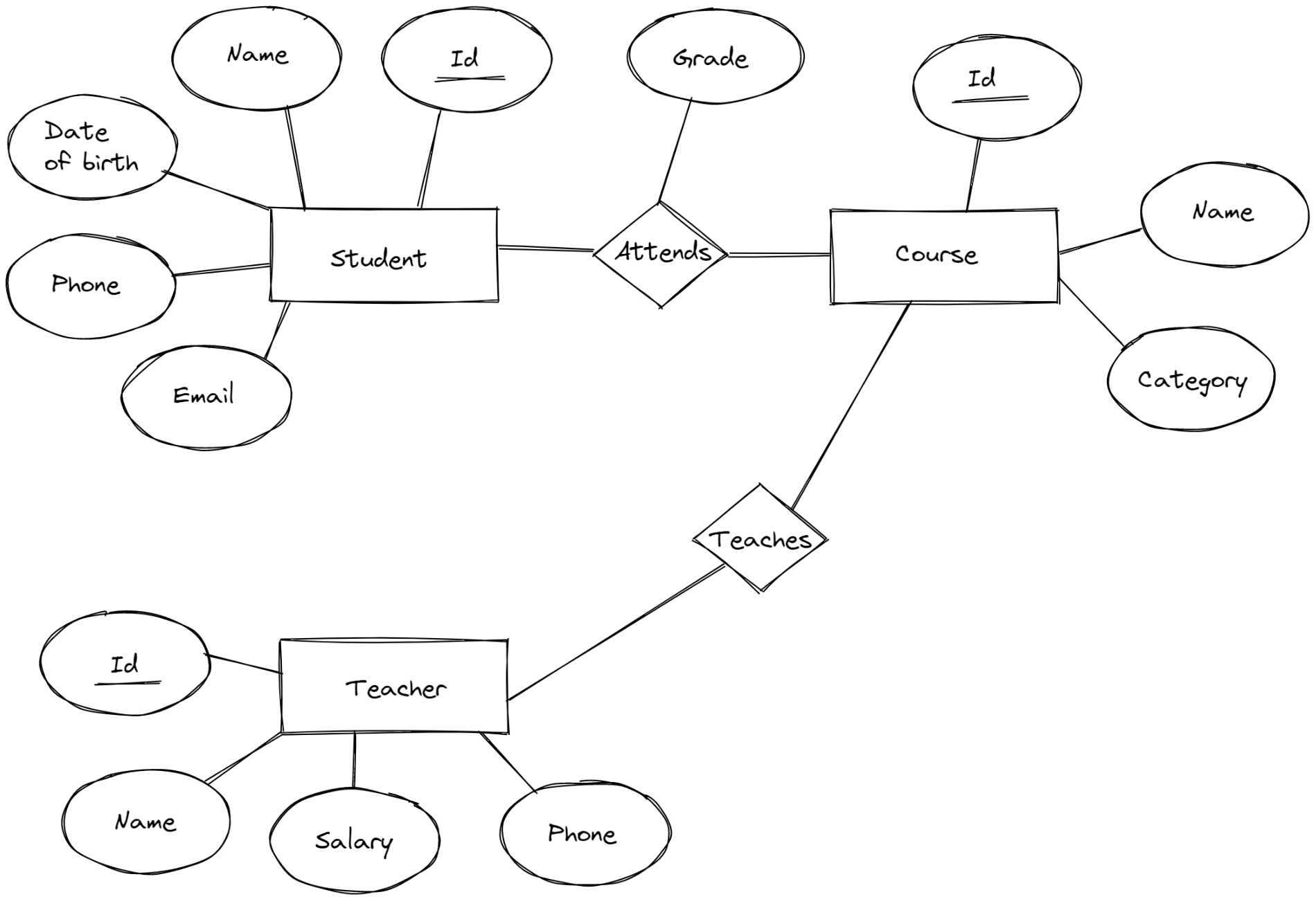
Attributes of Employee Entity are Name Id Address Gender Dob and Doj. Entities and their Attributes are. Name of the Entity is.
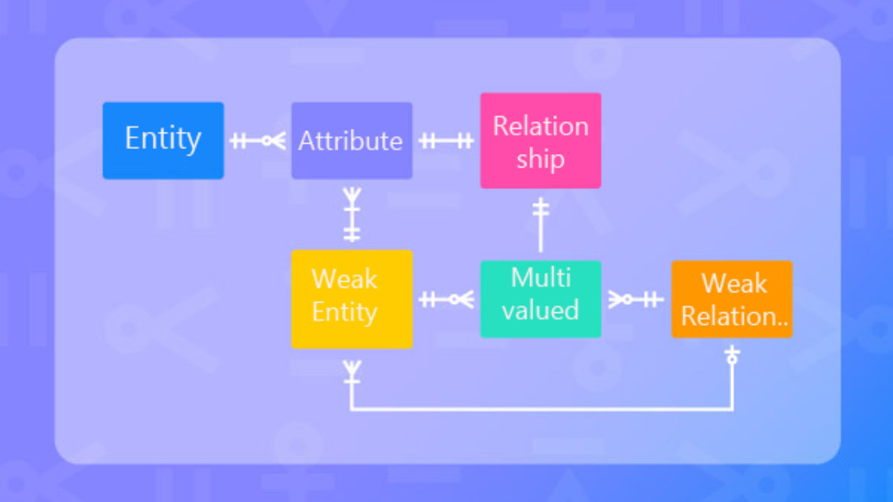
Weak entities are represented with double rectangular box in the ER Diagram and the identifying relationships are represented with double diamond. Recursive Relationships Arc relationships All can be modeled. Yes all constraints must be modeled and shown on the ER diagram No but you just explain them to the users so they can enforce them.
Aggregation is an abstraction through which we can represent relationships as higher level entity sets. Using ER diagrams one can easily created relational data model which nothing but the logical view of the. Since ER diagram gives us the good knowledge about the requirement and the mapping of the entities in it we can easily convert them as tables and columns.
Entities and their Attributes are. An ER diagram is not capable of representing relationship between an entity and a relationship which may be required in some scenarios. Fields of interest include a given paper models flat-foldability whether the model can be flattened without damaging it and the use of paper folds to solve up-to cubic mathematical equations.
The same entity participates more than once in the relationship. This bank ER diagram illustrates key information about bank including entities such as branches customers accounts and loans. Partial Key attributes are represented with dotted lines.
Since ER diagram is the pictorial representation of real world objects it involves various symbols and notation to draw the diagrams. The discipline of origami or paper folding has received a considerable amount of mathematical study. In this article we will discuss how to convert ER diagram to Relational Model for different scenarios.
This Company ER diagram illustrates key information about Company including entities such as employee department project and dependent. The creation of UML was originally motivated by the desire to standardize the disparate notational systems and approaches to software design. In set theory ZermeloFraenkel set theory named after mathematicians Ernst Zermelo and Abraham Fraenkel is an axiomatic system that was proposed in the early twentieth century in order to formulate a theory of sets free of paradoxes such as Russells paradoxToday ZermeloFraenkel set theory with the historically controversial axiom of choice AC included.
Explains ER Modeling normalization and identifying entities attributes relationships and keys. Convert ER diagram to relational tables Transform ER Diagram into Tables. Computational origami is a recent branch of computer science that is concerned.
An employee has a boss. It allows to understand the relationships between entities. The number of times an entity of an entity set participates in a relationship set is known as cardinality.
In the below ER Diagram Payment is the weak entity. And the bosschef is an employee too. Cardinality Ratios of relationships.
In Oracle SQL Developer Data Modeler you can select select how you want to map your subtypes. Often shown as an oval or circle. For example think of a work hierarchy.
Learn how to transform an entity-relationship ER Diagram into an equivalent set of well-structured relations. Prerequisite ER Model A relationship between two entities of a similar entity type is called a recursive relationship. Entity-Relationship ER Diagrams 10 CAR Make Year Model Registration State Number.
Entity Relationship Diagram. A property or characteristic of an entity. It allows us to understand the relationships between entities.
The Unified Modeling Language UML is a general-purpose developmental modeling language in the field of software engineering that is intended to provide a standard way to visualize the design of a system. Prerequisite ER Model To understand Structural Constraints we must take a look at Cardinality Ratios and Participation Constraints. ER model.
A flowchart is a type of diagram that represents a workflow or processA flowchart can also be defined as a diagrammatic representation of an algorithm a step-by-step approach to solving a task. Make sure the ER diagram supports all the data you need to store. 6 Process of Database Design.
Gaps in the fossil record mean that the origins of ancient animals such as jellyfish and corals have remained a mystery. Let us see one by one below. There are numbers represented by M and N written above the lines which connect relationships and entities.
A Computer Science portal for geeks. ER Diagram of Company. Rectangles are used to represent the entity in the diagram.
Derived attribute weak relationship and recursive relationship. After designing the ER diagram of system we need to convert it to Relational models which can directly be implemented by any RDBMS like Oracle MySQL etc. Cardinality can be of different types.
In other words a relationship has always been between occurrences in two different entities. As long as it provides the necessary. The flowchart shows the steps as boxes of various kinds and their order by connecting the boxes with arrows.
Now a long-awaited fossil discovery reveals key features of this group. Sometimes an entity refers back to itself.

Free Activity Diagram Tool Smartdraw Diagrams Software Architecture Diagram Software Projects Activity Diagram
What Is Descriptive Attribute In Er Model Quora
How Would You Explain Recursive Algorithm To A Layman Quora
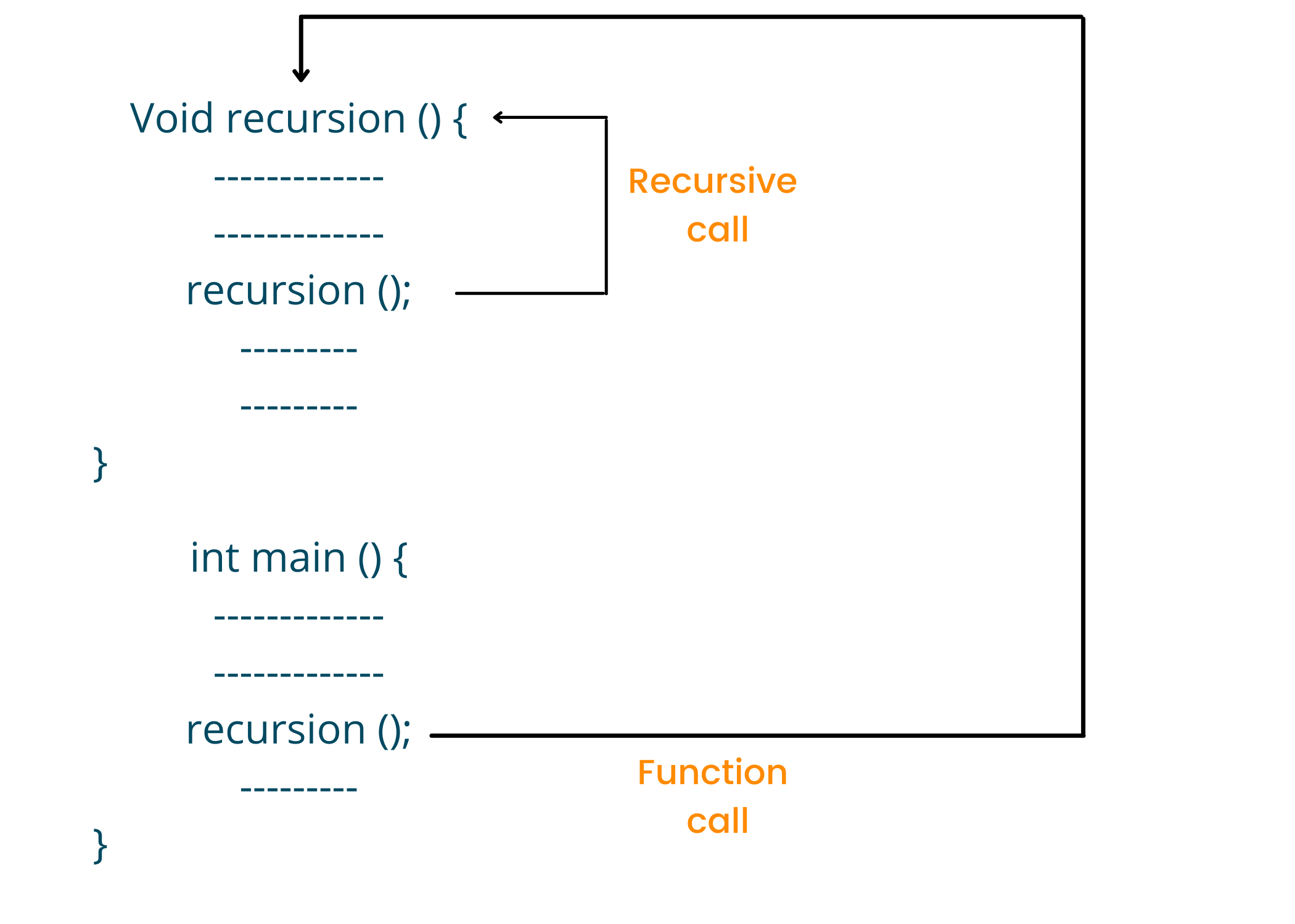
Recursion In C With Example And Code Favtutor

Hidden Markov Model A Comprehensive Overview 2021
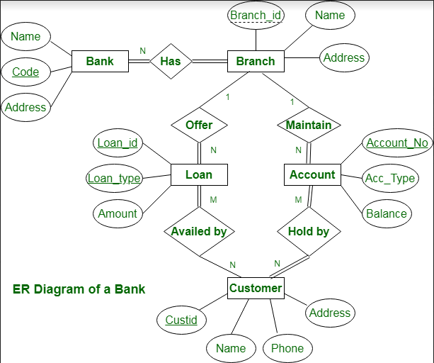
Er Diagram Of Bank Management System Geeksforgeeks

Database Design What Is The Next Best Ingredient To Add Database Administrators Stack Exchange
What Is Descriptive Attribute In Er Model Quora

What Is Descriptive Attribute In Er Model Quora

Machine Learning Projects For Beginners Using Matlab

How Do You Draw A Visual Paradigm Entity Relationship Diagram
Enterprise Modelling Wikiwand

How Do You Draw A Visual Paradigm Entity Relationship Diagram
What Are The Stages In Database Design Life Cycle Quora
How Do You Draw A Visual Paradigm Entity Relationship Diagram
Cisco Interview Questions And Interview Process

How Do You Draw A Visual Paradigm Entity Relationship Diagram